You are here

G5L Quad Relay

The G5L Quad relay board is designed for home automation, hydroponics, animated lighting and other control applications where you may need to switch one or more AC outlets.
Each section is powered and operated independantly for the most versatility. The board may be cut into as many as 4 individual units, each with their own mounting holes.
AC isolation from the control logic is provided in three steps: First the relay coil itself is isolated from the contacts. The coil is driven by a transistor, which is in turn driven by an opto-isolator package.
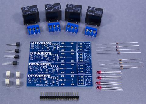
Here we have the parts:

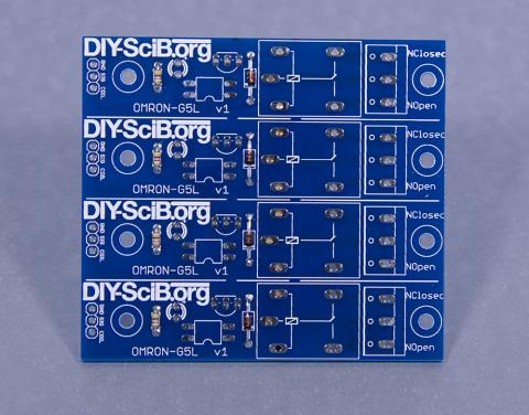
  • Blue PCB
  • 4 Relays (black or blue large cubes)
  • 4 3-Pin screw terminals (blue)
  • 4 transistors
  • 4 LEDs
  • 4 resistors
  • 4 Opto-isolator ICs
  • Male header pinstrip

 
Assembly

  1. Start by deciding if you will need to cut the board into smaller units. It is much easier to cut the board before mounting the parts. You can use a metal break, saw, or large tin snips. Cut along the silkscreen line between each relay unit.
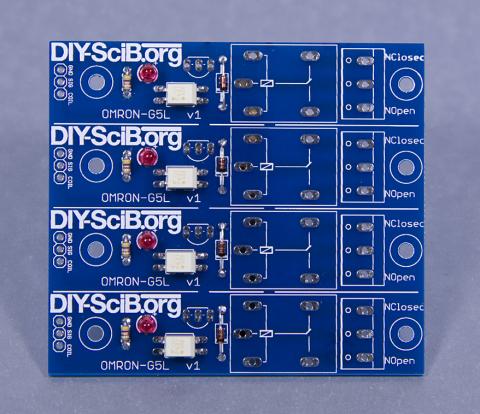
  2. Mount the resistors and diodes first. The resistor should in the space just above the first set of mounting holes (below the 'B' in the logo).
  3. The diode mounts near the boxed in area for the relay. The diode is the glass tube with wires. It must go in one direction only. Be sure the black stripe on the glass matches the marking on the silkscreen. See the photo below.

     
  4. Next mount the Opto-isolator. It has a dot printed on the top face, near one of the legs. This leg is pin 1. Pin 1 is closest to the V1 marking on the board. (The opto is rotated 180 degrees on the board).
  5. Mount the LED. There is a small flat space on the side of the LED body, which is closest to the short leg of the LED. The LONG leg of the LED is inserted on the side with the + mark on the board.

     
  6. Now mount the transistors. Be sure you match the flat face of the transistor with the image on the board.
  7. Now mount the pin headers (gnd, sig, coil). Cut the pin header into 4 groups of three and solder them in.
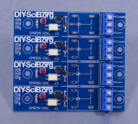
  8. Next we can solder in the screw terminals. Be sure the opening to the blocks face outwards from the board. Be generous with solder on the pins.

     
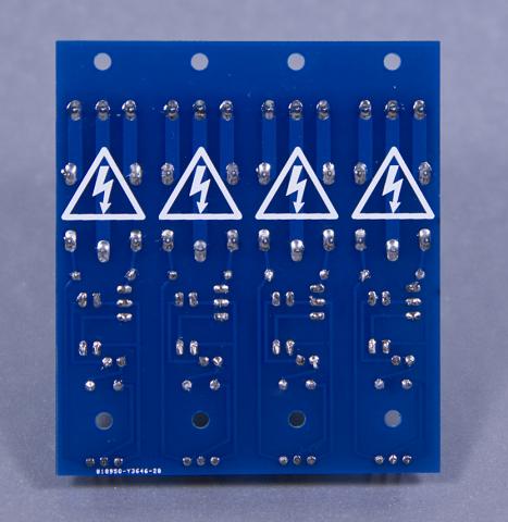
  9. Finally we can mount the relay package. Again, be generous with the solder on the pins and pads. They carry the load we wish to switch on and off. A poor solder job here will overheat.

     
  10. You should consider mounting hardware. Be sure to use standoffs that are not too long. You want to get the board up off any surface which might be conductive or trap water under the board, but not so high that you can fit a finger under the board. I use 5mm standoffs.

Diodes and resistors go in first. Build the board "smallest to largest."
 
Usage
The opto-isolator will operate with a control signal as low as 3 volts, and possibly up to 7 volts (I have not tried out the full operating range).
The relay coil requires 5 volts to operate. Thus if you are using 3.3 volt logic, you will need to also provide a 5 volt source to the coils.
To use a relay, you will need to connect the GND pin to your logic ground. Connect SIG to an output. Finally provide 5 volts to the COIL pin. When SIG is high, the LED will light and the relay will switch on.
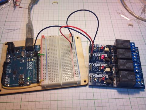
 
Wiring up a load
When switching AC loads, we typically want to switch the HOT line, rather than the neutral line. You can identify the hot line in the United States by the narrow pin on the plug which connects to the wall. In other countries, you will have to consult your local codes.
There are many ways to construct a cable. Here is just one:

  1. Buy a typical extension cord. About 3 feet from the plug, carefully cut about 2-3 inches of insulation off to expose the inner wires. Be careful not to cut the inner insulation.
  2. Identify the hot wire. In a flat cable, you can trace the wire easilly. In a round cable, you might get lucky (one wire is white, the other is black. Black is hot). You may have to cut both wires, use an ohm meter to identify the wires, and then repair the neutral wire.
  3. Cut the HOT wire and strip back 1/4 inch of insulation. Twist the wires tightly. You may want to add solder at this point, or crimp on a set of pins.
  4. Place a zip tie or a few wraps of tape around the cable near the cut, so as to provide some strain relief.
  5. Identify the wire which leads to the wall plug. Insert this wire into the CENTER pin of the screw terminal and tighten firmly. Check to be sure no loose coper strands are sticking out, and that the wire does not pull free.
  6. The other wire may be inserted into either NO or NC. NO means that when the relay is OFF, the circuit is open (also OFF). NC means that when the relay is OFF, the circuit is closed (The wires are connected, and so your load is ON).
  7. You may now plug your load into the socket, and the male end into the wall outlet.
  8. Be sure your load does not exceed 10 amps. You may want to add an inline fuse to your cord.

 
Assembly photos provided by Aperture Controls.

Comments

Hi Emery Premeaux.I like the thought that you want to save the world with Arduino.My immediate need is where can I either get the PCB for the G5L Quad relay or the schematic.Thanks
I am in Cape Town ,South Africa

This product is now available in my shop.
http://shop.diy-scib.org

Anwar,
Thank you for your comments. I have 8 boards in stock. I will have a webshop running in just a few days. Stay tuned. I only need to fix some issues with paypal Japan.

Theme by Danetsoft and Danang Probo Sayekti inspired by Maksimer