Solar X-rays:
![]()
Geomagnetic Field:
![]()
From n3kl.org


Here is a shot of the insides of my quiz show box.
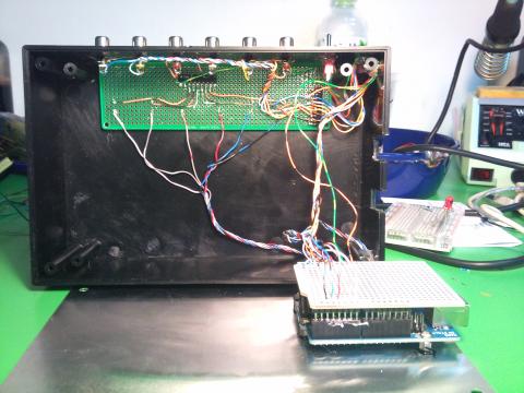
Lots of space in there! The arduino is bolted to the metal base plate. The shield is only there to provide a strong attachment point for the wires. Unfortunately, I only had solid core bell wire, so the cabling is quite stiff and hard to work with. Next time I'll use ribbon cable!
Burried under the wires are two SIP resistor packs. The LED pack is 2K ohms. I would have liked 500 ohms. They would be much brighter then. But I didnt have any in my inventory, and did not want to solder individual resistors. Common pin on the SIP goes to ground. Digital outputs on the Arduino send current through the LED, then through the SIP resistor pack.
The Buttons are mounted in seperate boxes. They are typical arcade style. I was fortunate to find a local shop with 6 colors. Each button has a long cable (at least 5 meters) so that I can use this kit in a school classroom. The player groups could be pretty far from the main box.
Buttons are tied high with another SIP resistor pack. In this case, the common pin on the SIP is connected to 5 volts. The resistor output is then tied to the analog inputs (I am using them as digital inputs). Also tied to the input is one leg of the switch (via the RCA connector on the box). The other end of the switch is connected to ground. When the switch is open, current flows into the input, registering a HIGH value in software. When the switch is closed, current takes the path of least resistance, going stright to ground, rather than entering the Arduino input pin. The software reads this as a LOW condition.
I have space in the box for future upgrades. I plan on installing a "correct" and "incorrect" button on the head unit, as well as a reset (so I can bypass the 5 second timer).
In addition to winner determination, the software also provides a serial message output. I hope to eventually connect it to a PC and write some gameshow software.
Below you will find the Arduino code:
/*
  Quiz Show buttons
  Emery Premeaux
  <a href="http://www.DIY-SciB.org

">http://www.DIY-SciB.org

</a>  This simple quiz show kit supports 6 buttons and LEDs.
  Buttons should be pulled high by resistors, and tied to A0-A6.
  LEDs are attached via resistors to digital pins 2 through 7.

  Default condition, all LEDs are light (It helps to know power is on ;)
  When a button is pressed, Three things happen:
    1: All LEDs are extinguished, and the winning LED is relit.
    2: A message is sent out the serial port. Use it to communicate with a PC game if you like.
    3: A 5 second timer locks out all other buttons. After the timer completes, the LEDs are reset and buttons
       are ready for input again.
 */

// Let's assign names
#define P1LED 2
#define P2LED 3
#define P3LED 4
#define P4LED 5
#define P5LED 6
#define P6LED 7

#define P1SW A0
#define P2SW A1
#define P3SW A2
#define P4SW A3
#define P5SW A4
#define P6SW A5

int P1, P2, P3, P4, P5, P6;

int WinDelay = 5000;

// the setup routine runs once when you press reset:
void setup() {
  // initialize the digital pin as an output.
  pinMode(P1LED, OUTPUT);
  pinMode(P2LED, OUTPUT);
  pinMode(P3LED, OUTPUT);
  pinMode(P4LED, OUTPUT);
  pinMode(P5LED, OUTPUT);
  pinMode(P6LED, OUTPUT);

  pinMode(P1SW, INPUT);
  pinMode(P2SW, INPUT);
  pinMode(P3SW, INPUT);
  pinMode(P4SW, INPUT);
  pinMode(P5SW, INPUT);
  pinMode(P6SW, INPUT);

  Serial.begin(9600);
}

// the loop routine runs over and over again forever:
void loop() {
 LEDsOn();
 P1 = digitalRead(P1SW);
 if(P1==0){
   Win(1);
 }
 P2 = digitalRead(P2SW);
 if(P2==0){
   Win(2);
 }
 P3 = digitalRead(P3SW);
 if(P3==0){
   Win(3);
 }
 P4 = digitalRead(P4SW);
 if(P4==0){
   Win(4);
 }
 P5 = digitalRead(P5SW);
 if(P5==0){
   Win(5);
 }
 P6 = digitalRead(P6SW);
 if(P6==0){
   Win(6);
 }
}

void Win(int Winner){
 switch (Winner){
   case 1:
     LEDsOff();
     digitalWrite(P1LED, HIGH);
     Serial.println("Player 1");
     delay(WinDelay);
     LEDsOn();
     break;
   case 2:
     LEDsOff();
     digitalWrite(P2LED, HIGH);
     Serial.println("Player 2");
     delay(WinDelay);
     LEDsOn();
     break;
   case 3:
     LEDsOff();
     digitalWrite(P3LED, HIGH);
     Serial.println("Player 3");
     delay(WinDelay);
     LEDsOn();
     break;
   case 4:
     LEDsOff();
     digitalWrite(P4LED, HIGH);
     Serial.println("Player 4");
     delay(WinDelay);
     LEDsOn();
     break;
   case 5:
     LEDsOff();
     digitalWrite(P5LED, HIGH);
     Serial.println("Player 5");
     delay(WinDelay);
     LEDsOn();
     break;
   case 6:
     LEDsOff();
     digitalWrite(P6LED, HIGH);
     Serial.println("Player 6");
     delay(WinDelay);
     LEDsOn();
     break;
 }
}


void LEDsOn (){
 digitalWrite(P1LED, HIGH);
 digitalWrite(P2LED, HIGH);
 digitalWrite(P3LED, HIGH);
 digitalWrite(P4LED, HIGH);
 digitalWrite(P5LED, HIGH);
 digitalWrite(P6LED, HIGH);
 }

 void LEDsOff (){
 digitalWrite(P1LED, LOW);
 digitalWrite(P2LED, LOW);
 digitalWrite(P3LED, LOW);
 digitalWrite(P4LED, LOW);
 digitalWrite(P5LED, LOW);
 digitalWrite(P6LED, LOW);
 }
Theme by Danetsoft and Danang Probo Sayekti inspired by Maksimer
Comments
I should mention that SIP
I should mention that SIP means "Single Inline Package."
Several resistors are mounted in a row, with one leg of each resistor all tied together to one common pin.