Solar X-rays:
![]()
Geomagnetic Field:
![]()
From n3kl.org


A few years back, I started on this weather station project while at the Tokyo HackerSpace (in our FIRST location). I had grand ideas for the project, but also knew I would likely have a few failures and re-designs. In my assessment, most of the sensors would be easy. Most of the sensors are 'digita' in nature, have no mechanical parts, and I have used on their own several times. The only challenge would be integrating them all in software, and building a suitable case for everything.
I knew the biggest challenge would be the mechanical parts associated with the wind direction and speed sensors. If we were to break it down, we really have ONE mechanical device. Atop this device are two possible head configurations (a vane or cups). Below the device we need to place some sort of position sensor. The head cap should be able to spin freely on a shaft, coupled to the magnet arm below, such that the rotation of the cap is readable by the sensor below. This device I will refer to as the spindle.
I initially thought of rotory encoders, potentiometers, and optical sensors. I finally settled on simple magnetic reed switches. This simplified the build, since for wind vane, 8 switches actually gives me 16 position resolution (dont forget that two adjacant switches may be activated at once). In the case of the anemometer, I only need one reed switch. Both boards should be easy to hack together, and I'd just need a magnet on an arm or disk rotating above the switches to activate them.
With that, I got on with figuring out how to build it inside some pvc pipe.
Now, in case you have not figured it out by the title, I ultimately abandoned the build process I am about to show here. So, if you are thinking of recreating my work, DON"T follow the process outlined in this blog!
The reasons I ultimately decided on a different construction technique:
What you CAN take away from this build, which I used in the final device:
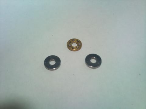
Everything is built around the shaft. Since I did not want to do any custom machining, I chose off the shelf shafts and bearings made by POWERS. The main shaft of each spindle is 3mm diameter by 150mm. I placed two 10mm (outside) bearings on the shaft. The precise locations, I can not recall, nore easilly measure at this point.
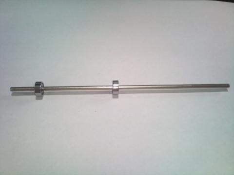
I had tried a smaller set of bearings, but they proved to be too grainy.
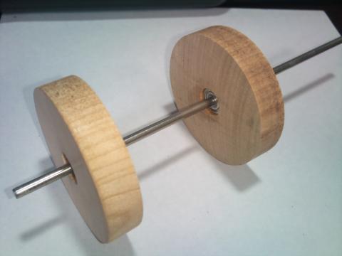
The thought here is that the wooden disks would act as bearing blocks, keeping the shaft centered. Here is what I was thinking:
So how did I get such perfect wooden disks you ask? Well, I started with very rough cut wooden disks made at the local hardware store. In some cases, the center holes were far from center. If mounted on a toy car, these things would cause a bumpy ride indeed. I needed to center up the hole, match up outer diameters, and size them down to fit inside a 40 mm PVC end cap.
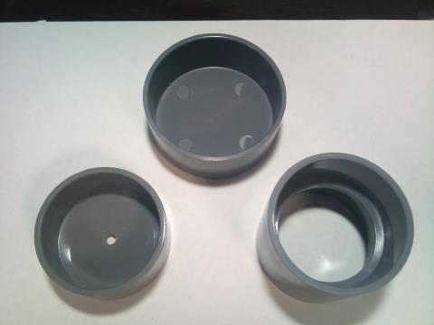
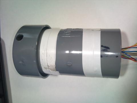
The original design used a 40 mm pvc pipe coupler (lower right), a 40 mm flat end cap with a hole drilled in the center (lower left), and a 50 mm flat end cap, which served as the top of the spindle, where the vane or cups would attach.
One of the wooden disks would fit inside the coupler and sit on the lip inside. The other would site right up against the inside top of the 40 mm cap. This is my first real fail here (besides using wood... dumb!). The wood block was pretty wide, giving me little room for a short bit of pipe between the cap and coupler to join them together. Later, in my demo video, you will see I just have them taped together.
Secondly, the coupler offers no way to mount the spindle to the structure. At first, I thought my only option for mounting the reed switch board was to sit it inside yet another cap, and mount it up with a short piece of pipe to the bottom of the coupler. Later I realized that If I had a well cut board, I could mount it on the lip of the coupler, just like the wood block. But still, how would I then attach the whole thing to the mast?
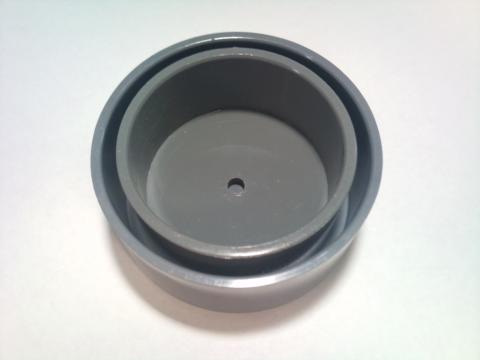
The idea here is that the 50 mm cap fits nicely over the 40 mm cap. It would act as a skirt around the spindle, protecting the mechanism from wind and rain, while still spinning freely over the top. I planned to use a thrust bearing between the two to both provide a gap and reduce friction or binding between the two.
Since the wood blocks were way out of round, I had to lathe them down to perfect circles on a perfect center. But I had no lathe. I had to get creative. What I eventually ended up doing was to thread them onto a large bolt. Thankfully, the original hole made at the hardware store was much smaller than the final hole required to mount the bearings in. So I was able to screw in a bolt with a bit of grip between the threads and the wood.
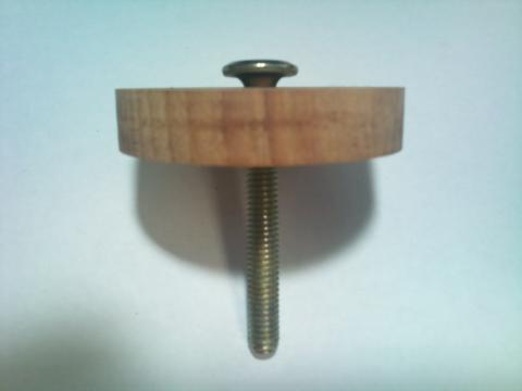
While this photo shows only one, I actually mounted both together.
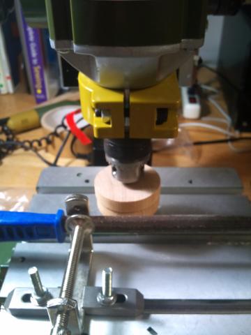
I then chucked this bolt into our small tabletop PROXON mill.
In order to lathe these down, I mounted a C clamp on the mill table, facing upright. In the C clamp I clamped a large file. The plan was to simply turn the file into the wood, which would file it down. I worked the mill spindle up and down the file, and just for the sake of the file I moved it along the axis parallel to it to spread the heat around. The sharp edge of the file actually worked to cut the wood a bit as well. The results were mostly good. As you can see in the photo of the wood in the bolt, there was a slight bevel that resulted. The file was not perfectly mounted in the clamp.
Here is a video of the process (I appologize for the extreme closeup of my teeth):
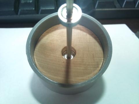
And here is the results:
So then I fit it all together, and held a few bits with tape. It spun really nicely, and everything seemed to be centered and smooth.
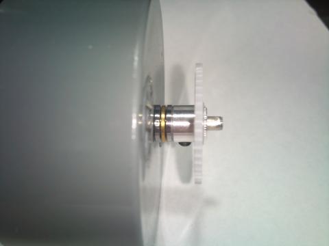
I placed the thrust bearing over the top and attached a POWERS gear.
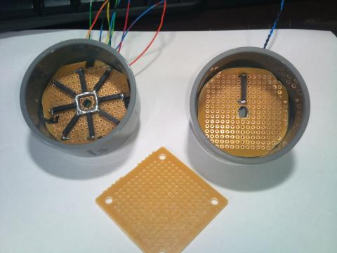
I found these really small surface mount reed switches. Well, they were mostly surface mount. In truth, they have a very small wire coming out the center. You have to bend them down to make them truly surface mount. In my final design, I actually had a cut out in the board they nestle into nicely. But for the prototype, I just put them on protoboards. One important note here is that there is a dot on the plastic on one end. This should face outward on all the switches. It places the moving contact as far from the center as possible. Otherwise, the magnet can activate more than two switches at a time. Often erratically.
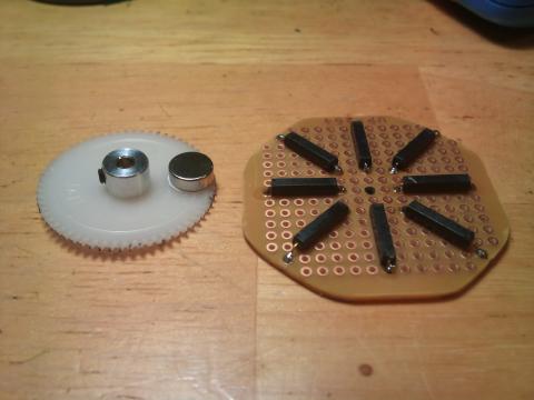
I arranged 8 switches on the vane board and 1 switch on the anemometer board. I had to nibble the boards down to some semblence of being round.
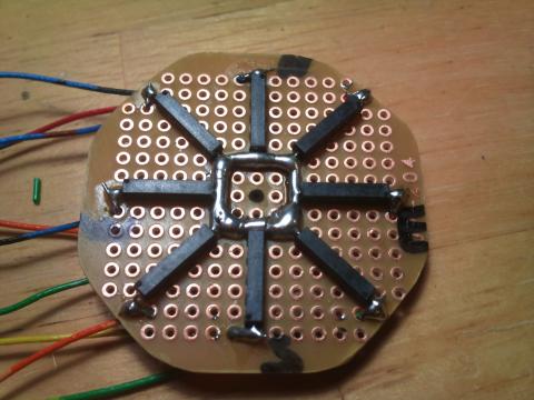
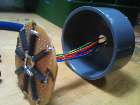
Once I had a good arrangement, I then had to wire it up. In the case of the vane board, I would need 9 wires (a common, and one per switch). I used solid core 'bell wire'. In hindsight, I wish I had used stranded ribbon cable. At any rate, the wires were fed through a hole in the bottom of the bottom end cap. Thus my second mechanical fail. The wires completely exit the spindle through a hole in the bottom, which totally exposed them to the elements and further complicated any mounting strategy I could have come up with.
I struggled with the making the magnet arm, trying to do so without any machining whatsoever.
My first thought was to use a shaft lever sold by POWERS. After getting it home, I discovered that It was too long to fit inside the pipe assembly without cutting it down.
My next thought was to make my own using a smaller gear, a paper clip, and a heavy dose of glue.
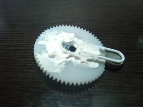
Ok.. Seriously... WTF was I thinking?
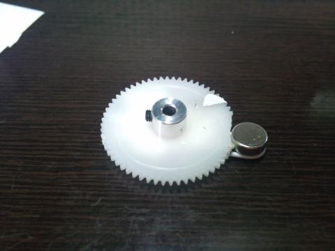
This also proved in testing to hold the magnet too far out from the center, providing unreliable switching action. My final (for now) design was simply to glue the magnet to the gear, as seen in the switch board section.
To mount the top cap, I went with some equally dumb choices. Somehow I had it in my head that I could perfectly center, balance, and glue a gear right into the inside of the cap. And could do so reliably with two different plastics and some silicon. Honestly, I sincerely hope I was NOT thinking that, and just stabbing at ideas, because I know better, and I KNEW better.
Here are the rather shoddy results:
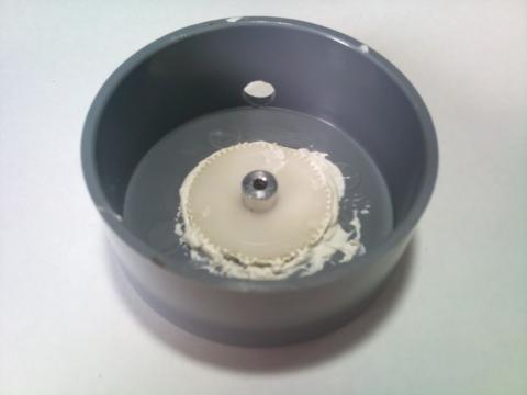
I had to drill a hole in the side of the cap to allow access to the allen key to lock the gear to the shaft. Uhh.. hello?! The whole Idea of this cap design was to shroud the top of the spindle to keep out wind, rain and dirt. ID10T error.
Here it is all assembled:
For grins and giggles, here is my rediculously long armed anemometer head. I used plastic eggs for cups and long thredded rods with nuts inside the cap.
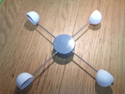
The new design uses MUCH shorter arms made from short bolts, but the same egg cups.
To be honest, it sorta looked impressive at the time, and it spun nicely. Until I noticed how out of balance it really was. Lots of wobble in the cap (poorly mounted). And mostly good but sometimes flaky switch signals (poor magnet arm design and off center switch board).
So, While I was happy with it as an experiment, it proved that I really needed to rethink a few things. My primary goal of utilizing off the hardware shelf parts as much as possible, without machining or difficult fabrication would have to be amended somewhat. I dissassembled the unit and kept the parts.
The magnet boards COULD be used as is, but attempting to get a perfect centered and circular board by hand would be difficult for anyone wishing to build the thing. In the long run, a perfectly machined pcb would perform MUCH better, be easier to dial in, and not really cost that much.
Wood was a poor materials choice. Like the switch pcb, perfectly machined parts would be needed. The simplest method would be to laser cut acrylic. I could get more fancy and better fit. The down side is that you wont find a laser cutter in poor countries, but assuming they have access to the pvc, the acrylic parts would only cost a few dollars, and ship in an envelope along with the switch pcb.
All in all, this version of the spindle is a total fail.
Stay tuned for the NEW design!
Theme by Danetsoft and Danang Probo Sayekti inspired by Maksimer