Solar X-rays:
![]()
Geomagnetic Field:
![]()
From n3kl.org


The machine has been in opperation a few weeks now and has had no real issues other than a minor code bug that was fixed quickly. It has processed a whole lot of membership payments and donations, with only one bill jam. Unfortunately, since the administrator on site did not have a key yet, they were unable to resolve the issue immediately. But, the member posted their problem on our google group and we were able to work out a solution. That is something that I think ANY cash handling machine has; when a bill or coin jams, there is not much the user can do. Write us a note and we will fix it.
The good news is that the eeprom accounting works really well, and we could verify the data immediately after appearing on site. I am glad I made it more rebust than the typical drink machine ;)
Anyway, I thought I would post some photos, since this is likely to be the last blog on the subject for a while (other than a video post). This post will cover the interior of the machine.
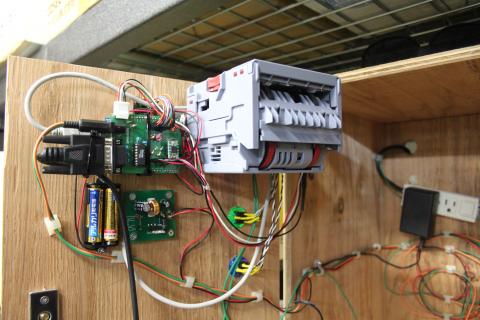
Here is a wide shot of the interior of the door. The big gray box is the back of the Innovative Technology NV10USB bill validator, programmed to accept Japanese bills. In the far side of it (close to the door hinge) is the interface cable. You can see the red, white and black wires looping over to the Arduino/shield stack, and plugging in with the white connector on the top left corner. For cleanliness, I wrap other cables around the insert plate of the bill validator.
To the left of the bill acceptor is the Arduino/shield stack. My green board is on top. There is a power connector (12 volts dc) to power up the validator. Below that is the RS232 cable from the thermal printer. You can see the MAX232 style IC just behind the board connector.
There is a small red button in the middle of the board, which enters the audit menus. Above that button is the interface cable to the VFD screen on the front of the machine. Below the button are the connectors for the front panel buttons and LEDs. Finally, just below and to the right of the button is the real time clock.
Below the shield stack is a 5VDC switching regulator board, designed by Tokyo HackerSpace member, James. This too is powered by the 12VDC power supply that powers the validator. The Arduino is powered off this 5 volt supply through a hacked USB cable. The reason for this is that after trials, 12 volts directly into the Arduino DC jack caused the onboard (linear) regulator to get unacceptably hot.
To the left of the power supply is the battery backup supply for the real time clock. It barely gets used. I suspect these two AA batteries will last several years.
Far left and low, just out of frame is the back plate of the door lock.
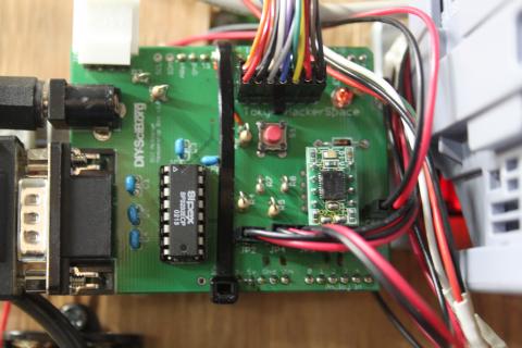
Here is a close up of the shield. I admit to making a few mistakes in the board layout, which have been since corrected on all the files. However, the board was manufactured before the cleanup, so on the bottom side, there are a few patches and bodge wires. No matter.. it works great.
I absolutely love this real time clock module, and have posted about it before. It is the RTC8564 mounted on a breakout from Akizuki Denshi.
Since I have 12VDC power and the serial port hanging over the Arduino's DC jack and USB plug, the shield is on log legs. The bulky serial cable puts some torque on it, so I had to zip tie the shiled to the arduino. HACKS!
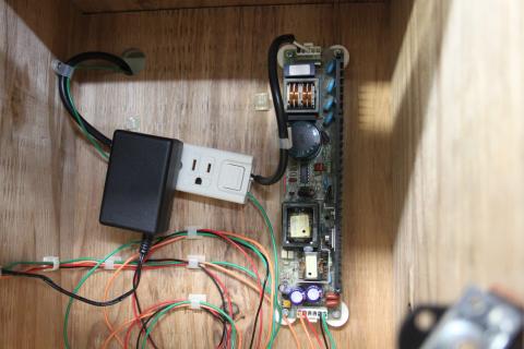
Most of the box is just a big open cavity of air for bills to fall into (my validator does not have a stacker). Way in the back we have the power system.
AC mains comes in through the hole on that big black cable (the green is a ground, since Japan does not belive in plug ground like the USA). It is wired into a friction lock power strip. A bit more cable through the friction lock on the other side takes AC to the switching DC supply. On the bottom side of the supply, orange and red carry +12VDC (one to the shield to power the BVA, the other to the 5VDC switching regulator). Black and Green carry ground. It is confusing with the mains ground and one of the DC supply grounds both being green. No worries.
Out of focus on the bottom right of the photo is the silver lock plate, mounted to a right angle bracket (black).
I should mention the lock here. It is a charactoristically Japanese lock, in that it is designed for sliding doors (usually in schools or old offices). The lock normally fits to one door, and the plate above is fit to the other. The key itself turns a screw, which is spring loaded and threads into the locking plate, jaming the two doors together. It works great in this application as well. The screws visible on the outside front of the box are superficial. They are just there to cover the hole the lock passes through. The lock is actually attached to the door from the back side.
Finally, I leave you with a video of how to use the machine.
Theme by Danetsoft and Danang Probo Sayekti inspired by Maksimer