Solar X-rays:
![]()
Geomagnetic Field:
![]()
From n3kl.org


In the image above, you can see a few of the pulses output by the NV10USB bill acceptor.
While we do have the option of reading the bill validation data over USB, the pulse output is just so much simpler to work with. It should be a simple matter to hook the output to the interupt pin of an Arduino and simply count out pulses.
I set the NV10 to output 1 pulse for 1000 yen, 5 pulses for 5000 yen, and 10 pulses for 10000 yen bills.
Each pulse starts as a logic high (provided by the host circuit). The signal pin actually pules the line low. So, the Arduino will need to detect the falling edge of the pulse.
As can be seen in the scope image, the pulses are 50mS low, seperated by 100mS high.
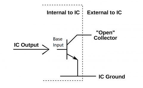
In the above Wikipedia image, we see the basic open collector configuration. The IC Ground is shared between the bill acceptor (everything inside the dotted line), and the Arduino.
The open collector pin is connected to the Arduino input. However, in state that it is in, we would never detect any change. It is low, or floating (near a logic low) condition now. When the bill acceptor applies current to the transistor base, the transistor is activated. But the output is still low. So, to solve this problem we need a pull up resistor.
We attach a resistor from the Open Collector 'output' (which, is actually, an input, switched to ground by the IC Output signal). The other end of the resistor is connected to a high voltage. This could be the 12 volt supply of the bill acceptor, but this would send 12 volts into the Arduino, which would be bad. Instead, we will use the 5 volt supply of the Arduino. We can also throw an LED in series for visual feedback.
Now, when the bill acceptor outputs a high pulse on the IC Output to signal a bill value, the base of the transitor receives that current. The transistor then allows current from the Open Collector input (5 volts of the Arduino) to flow to ground. This presents effectively a LOW signal at the Open Collector output (which, is really an input, yea?). The LED lights, and the Arduino sees a LOW signal.
Easy Peasy.
Here is a video:
Theme by Danetsoft and Danang Probo Sayekti inspired by Maksimer