Solar X-rays:
![]()
Geomagnetic Field:
![]()
From n3kl.org


One of the first hacks required for the Set Tob Box Data Sink project is to add the VGA option to the main board.
The original unit came with S-Video installed, which makes it great for a small video player thin client, but poor for reading text. I still may utilize the S-video output for a local visual interface. The idea being that I could switch to the S-video input on my TV and get a quick look at my data. I could implement some simple remote control UI with a few buttons and visualizations.
But before I can do any of that, I need to be able to look at the screen for long periods of time without my eyes bugging out. Even the simple linux shell looks horrid on S-video. Its really hard to read the text for any length of time.
So, After inspecting the area on the board where the VGA port would mount, I got to work. First I bought a couple of PCB mount VGA connectors. After returning from the shops in Akihabara, I sat down and chose the best connector option for the board.
Step one was to clear out the solder pads, which had been soldered over during manufacturing. I began cleaning out the pads with solder wick and an iron. One of the tricks here is to spread some solder flux onto the wick. This will help the solder suck up better. Next, put a dab of solder on the tip of the iron. Place the wick down on the pad you want to clean up, and press the tip down on top of the wick. Here is the interesting part: It is counterintuitive, but place some fresh solder onto the wick. Just a dab. This will get the flow going, and transfer heat better down into the solder on the pad below the wick. Its strange to ADD solder when your goal is to take away as much as you can, but it actually works great. Generous application of a solder sucker should finish the job up.
Another tip is to have a second iron available. You need a good fat tip on your main iron to transfer adequet heat to the pad and lift up most of that solder. However, sometimes you just cant get all the way down into the hole. A second iron with a needle thin tip is really nice to act as a sort of "hot punch" to clear that last bit. Also, its nice to smooth out the rough solder edges. Use it sort of like a file, ringing the edges to clean them up.
After clearing all the pads, it was time to fit the connector. And here is where I ran into the first of a series of problems.
First issue: This board had a header connector mounted just behind the VGA pads. The VGA connector would not mate up to the pads until I removed the shell wrapped around the other connector. My guess is that it serves as a cable option for the VGA connector, in case the manufacture wanted to use a panel mount VGA port. I didnt feel like pulling all the pins, so I just pulled the plastic shell up with a pair of good needle nose pliars. With it out of the way, the VGA connector body slides down, with the second connector's pins right up against it. A tight fit, but good enough for me.
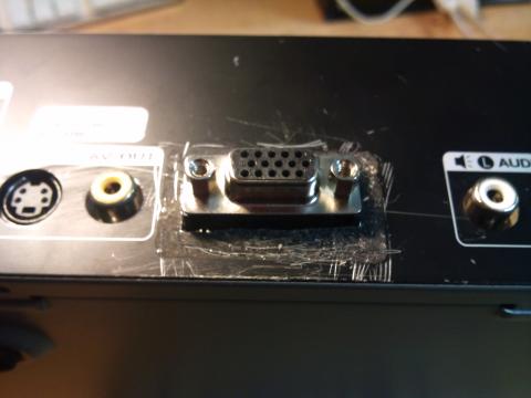
The next issue was actually lining up the VGA pins with the pads. The pins were fat, and the pads still a bit muddled from old solder. I found it helped a lot to pry the shell hold down clips up. These clips penetrate the board and are soldered down to keep the shell in place. Getting them temporarilly out of the way made it much easer to seat the connector. Once in place, I just bent them back down and pushed them through the board. After that, I just needed to solder it all in.
As can be seen above, the video tested out perfect! Now I just need to cut a hole in the panel to fit the jack.
Or so I thought.
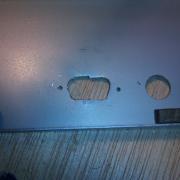
AS ou can see, I spent no small effort cutting the shell outlet. First I set the panel against the case where I suspect it would line up and traced the shell with a sharp machinist's needle. I then drilled the four corners, and nibbled out the shape using a panel nibbler. Its not perfect, but this is all pre filing. I did a preliminary check of the fit, only to discover that the entire VGA connector extended too far off the board! There was no way the panel would go on. Time for plan B.
I ended up using the panel nibbler to cut away a rectangle large enough for the whole VGA connector to pass through. It sticks out the back of the case, and is very obvously NON factory spec, but it works just fine!
Theme by Danetsoft and Danang Probo Sayekti inspired by Maksimer