Solar X-rays:
![]()
Geomagnetic Field:
![]()
From n3kl.org


This simple flashlight can suck every available bit of power remaining out of 'dead' batteries.
When your AA battery no longer has enough power to run your electric tooth-brush or power the tv remote, pop it into this flashlight to get some more use out of it before chucking it in the recycle bin.
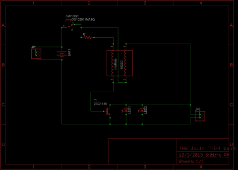
The circuit is described in detail on this wikipedia article, and is a direct copy of the schematic shown.
If you just want to build it, feel free to skip ahead.
This little kit came about through a series of fortunate events at the Tokyo HackerSpace. Some time back, Natsuki Tanaka of Okayama MakerSpace (and long time THS friend) mentioned an UNBELIEVABLE listing on Yahoo Auctions Japan. The auction was for "15-20 small to medium boxes filled with electronic components. Buy must arrange pickup. We will not ship packages." What was shocking was the fact that the starting bid stood at 5000 yen (about $50 USD at the time). Being on the south end of Japan, Natsuki could not arrange pick up himself, but suggested that THS should place a bid. In utter disbelief at what I saw in the photos, I arranged a bid through one of our members. Quite shockingly, we actually WON the bid, at 5000 yen!
A week later, we were driving out with a delivery truck to pick up what I had assumed was 20 small boxes. What I saw was... overwhelming. For the first time in 7 years living in Japan, "small" meant large, and "Medium" meant the American equivilant of "Super Sized!" These boxes were HUGE. It ended up taking us THREE trips in a delivery van to get it all moved. Check out our photos on Facebook for more details.
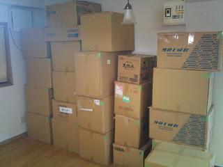
This is about half of the auction boxes, at the pickup site. More boxes were behind me, as well as waiting outside on the patio.
Fast forward about a year and a half. We had been wracking our brains thinking of stuff to do with all these parts. In the midst of that, we moved the hackerspace to a new location. In that time, new members joined us and began contributing to the space, as well as organizing us. Ed, one of those new members, offered to start cataloging all of our components. He had also mentioned wanting to whip up a Joule Thief. One day he grabbed one of the many clamp on cable choke ferrite cores, dissassembled it, and began winding a coil for his Joule Thief. The following week he brougt in his finished project.
Around the same time, I had been going through components and identifying things that may be better off in the recycle bin than on our shelves. I came across some power supply common mode chokes. By some, I mean, a bag of at least 50. Knowing the street value of such an item, I was very resistant to the idea of putting them in the 'Vortex of Doom,' but I also knew no one in the space was going to be building up 50 plus power systems any time soon. What to do.
I took a few home and begin playing around with them. What could the be used for that might be something we could make a kit out of? I tried using them as a current transducer. Not really optimal (I never did get it to work right, but not giving up on the idea just yet). I suddenly remembered Ed winding his coil and realized that the dual mode choke is essentially the same configuration. The only real difference is that Joule Thief coils are usually wound parallel to each other around a round coil. The choke is physically different configuration, but amounts to the same thing. I tried wiring up a Joule Thief with one, and other than needing to swap two wires, It fired right up!
The Joule Thief Flashlight kit is the final results of that unintentional collaboration.
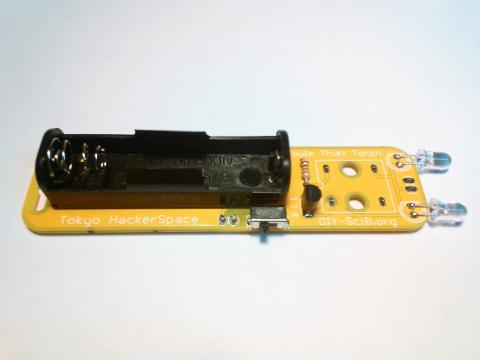
To start, let's first verify the parts. It is a small list of components:

It is pretty obvious where each component goes, since no two are alike, and can only physically fit in one location. So rather than a step by step narration, I will just give a photo assembly guide. Some things to be cautious of:
Eagle files are available on github.
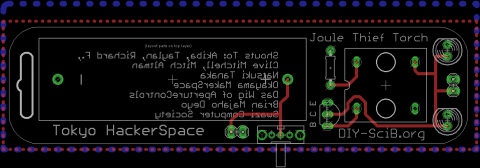
Shout outs are:
Akiba, Taylan, Richard of THS, Clive Mitchell (the creater of the Joule Thief), Mitch Altman (if you don't know this guy, google him!), Natsuki Tanaka, Okayama MakerSpace, Eric Hellwig (my brother) of ApertureControls, Brian Deyo of Peace Corps Swaziland, and the Swazi Computer Society.
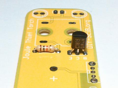
Step 1: Solder in the resistor
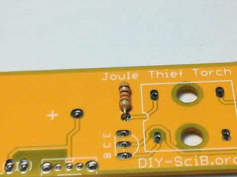
Step 2: add the transistor
Step 3: The switch
Bend the large tabs to hold it in place while you solder, and give a real solid phyical mounting.
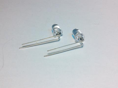
Step 4: Bend the LED legs
Notice the direction they are bent. Take notice of the short leg. Verify the flat spot on the silk screen of the circuit board.
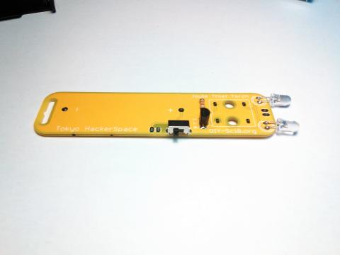
Step 5: Solder the LEDs
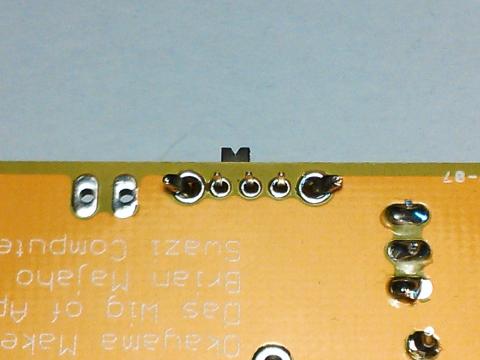
Step 6: The battery case
Notice the + and - markings on the circuit board. The spring of the case is close to the lanyard strap hole.
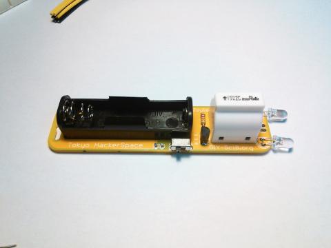
Step 7: The all important coil
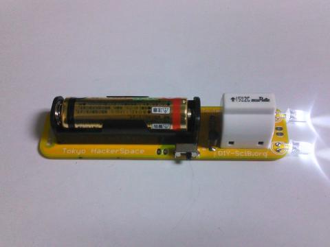
It's finished! Now chuck in an old battery and flip the switch!
Theme by Danetsoft and Danang Probo Sayekti inspired by Maksimer