Solar X-rays:
![]()
Geomagnetic Field:
![]()
From n3kl.org

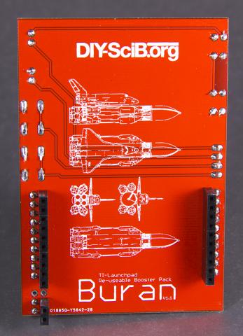
The Buran was the Soviet Space program's answer to the US Space Shuttle: A reusable space craft with immense flexibility, adaptability and modularity.
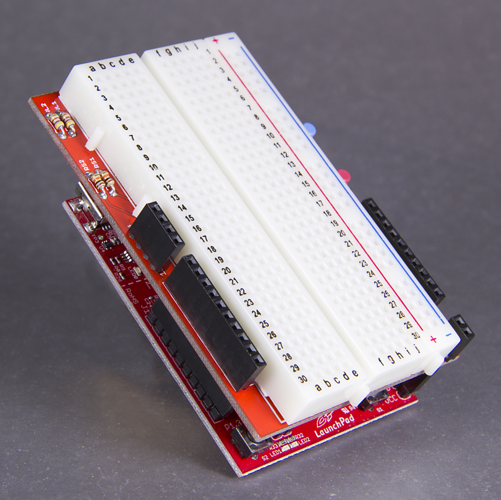
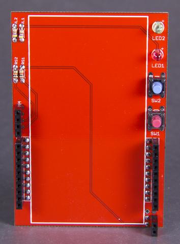
The TI Buran booster pack is a reusable prototyping pack for the TI-Launchpad. It offers two buttons, to LEDs and a large breadboard prototyping area for your own experiments, projects and demonstrations.
Ideal for use with the Energia programing environment.
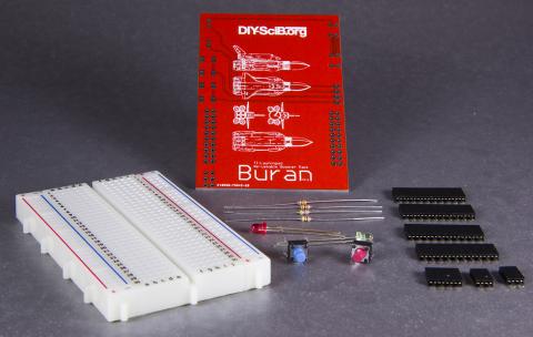
Step 1: is to verify the parts. You should have:
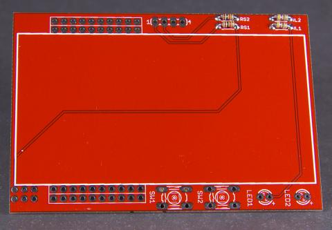
Step 2: Insert and solder the resistors. Two 470 ohm resistors go in RL1 and RL2. Two 10K resistors go in RS1 and RS2.
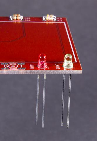
Step 3: Insert and solder the LEDs. Be sure the flat or short leg faces the LED label. Color placement is your own preference.
Step 4: Insert and solder the buttons. Again, color placement is your choice.
Step 5: Place female headers on your TI-Launchpad. You need two 10-pin headers and a 2 or 3 pin header. The two 10 pin headers go on either side of the board. The two (or three) pin head goes on the power connector. If you have a two pin header in your kit, place it on the three pin header, such that it is closer to the edge of the board (on VCC and the first GND pins).
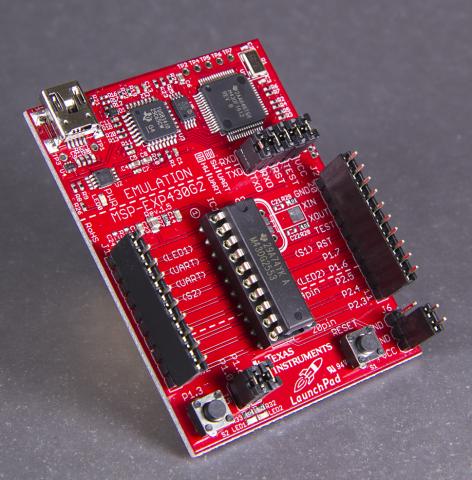
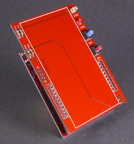
Step 6: Place the Buran board over the Launchpad. Be sure the silkscreen image of the real Buran space craft faces the launchpad. Solder all the headers to the Buran PCB.
Step 7: We now need to install the second set of pin headers, which will be accessable on the top. Remove the Buran board from the launchpad and flip it over. You now have the tricky job of soldering in the top side female headers. Again, you will insert two 10-pin headers, as well as a 4 pin header and a 2 or 3 pin header. Insert them from the top of the board (no rocket image). My suggestion is that you put a bit of solder on one pad. Then line up the header in the remaining holes. Holding the board and header in one hand, reheat the solder of the pad and set the header in place. Then hit all the other pins with solder. Another method is to skip step 7 and go straight to step 8. After step 8 is complete, return to step 7, but do not remove the board from the launchpad. You can then set the whole assembly upside down on your desk and carefully solder the pins.
Step 8: Set the board aside for a moment, and take a look at the breadboard. Set it so that the "abcde fghij" markings are at the top. There are two power strips (one on each side of the board). We need to cut the LEFT side power bar off. Simply bend it back so it snaps off the main breadboard area. Now cut the tape holding it together with a knife.
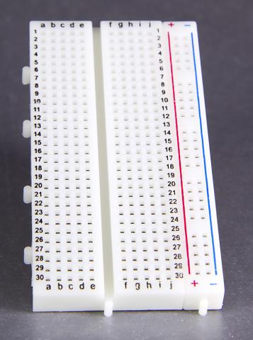
Step 9: Peel the backing off the breadboard and stick it to the face of the Buran board. IT should be situated so that the power bar is on the side of the 2 or 3 pin header of the Buran board. Be sure to center the breadboard on the Buran PCB.
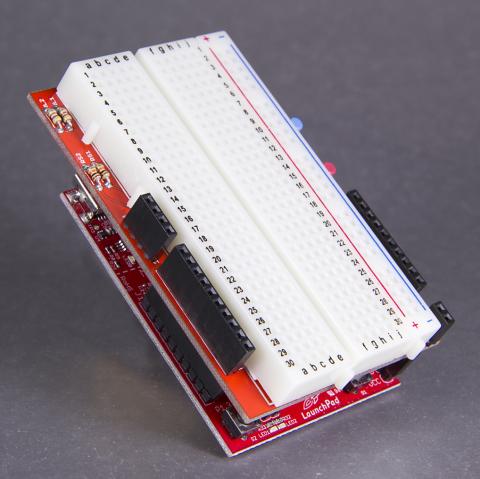
Step 10: To provide power from the launchpad to the breadboard, you will need to provide two jumper wires. If you have a kit of precut breadboard wires, the short lengths of yellow and orange wire are usually the best fit. The lowest pin on the 3 pin header is for VCC. Connect this to the + (red) strip of the power bar. The second and third pins on the header are ground. Connect the second (middle) pin to the - (blue) strip. DONE!
USE
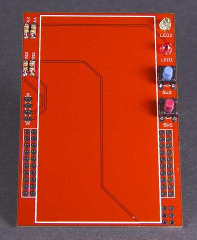
The 4 pin header gives you access to the buttons and LEDs.
To drive LEDs, simply connect from the 4 pin header to an output pin (active low. The output at 0 turns on the LED).
To read a switch, simply connect from the 4 pin header to an input pin (swithes are pulled high. Thus, unpressed = 1, and pressed = 0).
When positioned with the "abcde fghij" towards the top, the 4 pin header assignment from top to bottom is:
(followed by the 10 pin header)
To put it another way, the two LEDs and the two switches are in a row. They correspond one-to-one with the 4 pin header on the other side. The top pin connects to the top LED. The bottom pin connects to the bottom button.
It should be noted that the launchpad's native LEDs and button remain functional. So, with the Buran board attached, you have access to three buttons and four LEDs.
Theme by Danetsoft and Danang Probo Sayekti inspired by Maksimer
Comments
Thank you to Aperture
Thank you to Aperture Controls for the fantastic photographs and assembly testing.
PATCH REQUIRED for version 1.1 boards
The TI Launchpad has two ground pins. Unfortunately, only one was connected by the planer fill in the Eagle layout. Version 1.2 boards have this problem fixed.
For version 1.1, the solution is simple. Just solder the middle ground pin to the top ground pin to complete the circuit.
I appologize for this relatively mundane and unfortunate error.