Solar X-rays:
![]()
Geomagnetic Field:
![]()
From n3kl.org


I dug out my FreeCAD drawings and made images of the drawing. I am adding those images now, and will link the mechanical file. You can open it in FreeCAD, explore the mechanical design of the spindles, find the parts and make your own modifications.
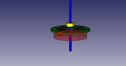
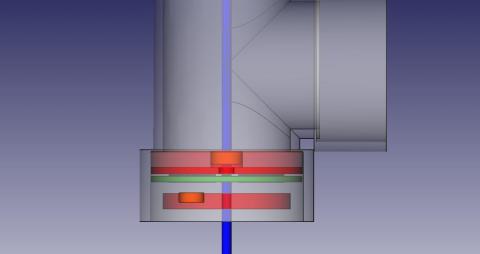
The green PCB holds 8 micro reed switches, surface mount resistors, and a 8 channel digital I2C expander IC. The saft (blue) rotates in a set of two bearings (yellow). A magnet (orange) is held by an acrylic disk (red) which is press fit to the shaft. As the magnet rotates, it pulls the reed switch/s nearest it closed. This wind vane PCB with 8 switches has a resolution of 16 directions, since two adjacent switches may be pulled closed by the magnet.
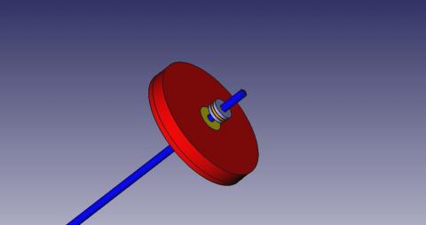
Both bearings (yellow) are held in place by a two part acrylic disk bearing seat (red). The centering disk is 5mm thick, to match that of the bearing. It's center hole is cut to the outside diameter of the bearing. The base disk is 2mm thick. It's center hole is cut larger than the shaft, but smaller than the outside diameter of the bearing.

![]()

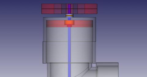
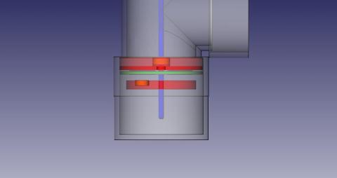
Two 5mm "star disks" are press fit to the top of the shaft. It is the 50mm PVC cap that press fits over these the drives the shaft assembly. Between the star disks and the spindle main body is a thrust bearing (silver-orange-silver).
The 50mm 'hood cap' overhangs the 40mm cap, preventing wind from blowing dust or rain into the space above the top of the spindle body, thus keeping the whole assembly clean and dry. It is to the 50mm cap that arms are attached for wind cups, or a vane and weighted point for a wind vane.
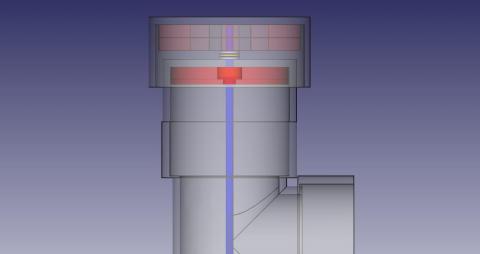
Wiring from the PCV is passed through a hole drilled through the bearing mounts (after glued in place. Fit the hole accurately to the cable assembly). Cabling passes through the middle portion of the T into the logic module's T housing.
Finally, an end cap seals up the bottom end. With all caps in place, the spindle is rain and wind proof.
One revision I have made to assembly regards the bearing seats. It is advisable to place the 2mm seat plates on the outsides of the shaft. That is, the 5mm disk goes into the T first. The shaft is passed through both disks and the bearing positions adjusted. Finally, place the seat plate to hold the shaft in place vertically in the spindle. This method is much more repairable. In addition, the top bearing assembly SHOULD be mounted inside the T, rather than inside the top cap. Provided your shaft is straght, you should not have any friction on the top cap hole, and little if any wobble in the head assembly.
I made the mistake of mounting my first shaft with the 2mm seat disks BETWEEN the bearings. This makes it very difficult to dissassemble, as the bearing first has to be pulled off the shaft before it can thread out of the plates.
Theme by Danetsoft and Danang Probo Sayekti inspired by Maksimer